



A Python library for characterizing and using the CCD cameras developed by Marshall Space Flight Center.
The sounding rocket team at MSFC builds CCD cameras for solar instruments flown on sounding rockets. This library reads the FITS files those cameras produce, and models the camera and sensor well enough to turn a raw readout into a calibrated image.
Every array in this package is a named_arrays array, so the axes carry names such as detector_x rather than integer positions, and an image loaded from disk broadcasts against the other arrays in the stack without reshaping.
More information is available in the documentation.
msfc-ccd is available on PyPI and can be installed using pip:
pip install msfc-ccdfits.open(), which loads one FITS file, or a sequence of them, into a single object.SensorData, an image or a sequence of images as read from the sensor, along with the operations that calibrate it:.taps,.active,.unbiased, and.electrons.TapData, the same image split into the four quadrants read out by the four taps of the sensor.ImageHeader, the FITS metadata for each image, including the exposure time, the sensor and FPGA temperatures, and the timestamps.CameraandTeledyneCCD230, models of the camera and its sensor, carrying the parameters needed to calibrate an image: gain, dark current, readout noise, charge transfer efficiency, and the exposure timing.samples, a handful of real FITS files gathered from the cameras, used by the examples below.
An image pairs pixel values with the header that describes them.
SensorData stores the pixel values in .outputs, in data numbers (astropy.units.DN), on axes named by .axis_x and .axis_y, and the FITS metadata in .inputs as an ImageHeader.
Loading many files at once adds another named axis to both, so a sequence of images is the same type as a single image.
The sensor is read out through four taps.
Each quadrant of the CCD has its own amplifier, so a raw frame is really four images side by side, each with its own bias and gain.
.taps splits a frame into a TapData with tap_x and tap_y axes, and .from_taps() reassembles one, flipping each quadrant back into the orientation of the sensor.
Blank and overscan columns measure the bias.
Each tap reads out 50 blank columns before the light-sensitive pixels and 2 overscan columns after them.
Those columns see no light, so their mean is an estimate of the bias for that tap.
.active trims them away, .unbiased subtracts the bias they measure, and the two compose: image.taps.unbiased.active.
Converting to electrons needs a gain.
.electrons multiplies by Camera.gain, which is usually different for each tap and has to be measured.
A Camera constructed without one, which is what fits.open() uses by default, has no gain to apply, and raises a ValueError naming the missing parameter rather than guessing.
Supply your measured value with msfc_ccd.Camera(gain=...) before converting, remembering that the gain differs from tap to tap.
Load and display a single FITS file.
import matplotlib.pyplot as plt
import named_arrays as na
import msfc_ccd

# Load the sample image
image = msfc_ccd.fits.open(msfc_ccd.samples.path_fe55_esis1)

# Display the sample image
fig, ax = plt.subplots(
    constrained_layout=True,
)
im = na.plt.imshow(
    image.outputs.value,
    axis_x=image.axis_x,
    axis_y=image.axis_y,
    ax=ax,
);
Measure the bias of each tap, and remove it.
# Split the frame into the four tap images
taps = image.taps

# Each tap has its own amplifier, and so its own bias
taps.bias().outputs
ScalarArray(
ndarray=[[3571.56153846, 3807.21634615],
[3652.99519231, 3446.92692308]] DN,
axes=('tap_y', 'tap_x'),
)
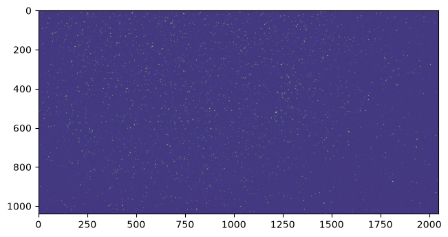
# Subtract the bias and trim the blank and overscan columns
corrected = image.from_taps(taps.unbiased.active)

# Display the corrected image
fig, ax = plt.subplots(
    constrained_layout=True,
)
im = na.plt.imshow(
    corrected.outputs.value,
    axis_x=corrected.axis_x,
    axis_y=corrected.axis_y,
    ax=ax,
    vmin=-20,
    vmax=100,
);
Inspect the header of an image.
header = image.inputs

print(f"serial number:  {header.serial_number.ndarray}")
print(f"exposure:       {header.timedelta.ndarray}")
print(f"start:          {header.time_start.ndarray}")
print(f"FPGA temp:      {header.temperature_fpga.ndarray}")
serial number: 6
exposure: 1.999999975 s
start: 2017-07-06T16:36:48.449
FPGA temp: 38.881396484375045 deg_C
Inspect the sensor model that the calibration steps rely on.
import astropy.units as u

sensor = image.camera.sensor

print(f"sensor:          {sensor.manufacturer} {sensor.family}")
print(f"active pixels:   {sensor.num_pixel_x} x {sensor.num_pixel_y}")
print(f"blank/overscan:  {sensor.num_blank} / {sensor.num_overscan}")
print(f"readout noise:   {sensor.readout_noise}")
print(f"charge transfer: {sensor.cte}")
print(f"dark current:    {sensor.dark_current(263 * u.K):0.3f} at 263 K")
sensor: Teledyne/e2v CCD230-42
active pixels: 2048 x 2064
blank/overscan: 50 / 2
readout noise: 4.0 electron
charge transfer: 99.9995 %
dark current: 1.039 electron / s at 263 K
Install the package in editable mode along with its test dependencies, and run the test suite using pytest:
pip install -e .[test]
pytest
The sample FITS files are stored with git LFS, so git lfs install is needed before the tests and the documentation examples will work.
This project is formatted using black and linted using ruff, both of which are checked by continuous integration:
black .
ruff check .
To build the documentation locally:
pip install -e .[doc]
sphinx-build docs docs/_build/html